Gait Rehabilitation Device
A three revolute-prismatic-spherical parallel manipulator gantry system with real-time control, IMU integration, and servo-driven actuation.
Gait Rehabilitation Device
Overview
A three revolute-prismatic-spherical parallel manipulator gantry system with real-time control, IMU integration, and servo-driven actuation.
Project Overview
The 3-RPS (Revolute-Prismatic-Spherical) gantry system is an advanced parallel manipulator designed for precise three-degree-of-freedom positioning (X-Y translation with rotation). This project demonstrates a real-time embedded control system with IMU integration, multi-cog architecture, and joystick-based human input handling on the Propeller microcontroller platform.
System Architecture
Mechanical Configuration
The system utilizes three independently actuated RPS kinematic chains arranged in a 120° pattern around the base. Each chain consists of:
- Revolute Joint: Base rotation axis
- Prismatic Joint: Servo-controlled linear extension
- Spherical Joint: Platform attachment point allowing 3DOF orientation
This parallel architecture provides:
- High structural stiffness with distributed load paths
- Synchronized three-point support for platform stability
- Full 3DOF platform control (X, Y, rotation)
Key Components
Propeller Microcontroller
- 8 Independent Cores (Cogs): Enables true parallel processing
- Real-time Control: 100MHz operation without OS overhead
- Pin-out: 32 I/O pins for servo and sensor interfacing
Motor Control
- RPS Leg Actuators: Three servo motors (Pins 12, 13, 14)
- 1400 microseconds: Fully retracted (down)
- 1500 microseconds: Neutral position
- 1600 microseconds: Extended (up)
- Gantry Motors: Linear actuation (Pin 15)
- 1400 microseconds: Left movement
- 1475 microseconds: Neutral/stop
- 1600 microseconds: Right movement
Sensing System
IMU Sensor (MPU-6050) integrated via I2C interface:
- Accelerometer: ±2g range with 16384 LSB/g sensitivity
- Gyroscope: ±250°/s range with 131 LSB/°/s sensitivity
- Temperature Sensor: Onboard thermal monitoring
- Real-time Orientation: Roll and pitch calculation from sensor fusion
Analog Joystick Controller:
- 3-axis analog input via ADC (Pins 18-21)
- Threshold-based control mapping:
- Upper threshold (>3.0V): Forward/up/rotation positive
- Lower threshold (<2.0V): Backward/down/rotation negative
- Dead zone (2.0-3.0V): No command
Software Architecture
Multi-Cog Design Pattern
The control system uses Propeller’s unique multi-cog architecture for true parallel execution:
Main Cog (cog0):
├─ System initialization
├─ IMU calibration
└─ Monitoring loop (500ms cycle)

Servo Control Cogs (cog1, cog2, cog3):
├─ RPS Leg 1 PWM generation
├─ RPS Leg 2 PWM generation
└─ RPS Leg 3 PWM generation

Gantry Control Cog (cog4):
└─ Platform XY actuation

Input Processing Cog (cog5):
├─ ADC sampling (joystick)
├─ Threshold logic processing
└─ Command state management
Control Flow
1. Initialization Phase
mpu6050_init()      // Initialize I2C and IMU registers
cogstart(...)       // Launch servo control cogs
cogstart(...)       // Launch input processing cog
calibrate_gyro()    // Collect 1000+ samples for offset determination
2. Real-time Operation
- Servo Cogs: Continuous PWM pulse generation (20ms cycle)
- Input Cog: 50ms ADC sampling interval
- Main Loop: 500ms monitoring/telemetry output
3. Command Processing
Joystick input → ADC Conversion → Threshold Logic → Servo Command
Implementation Details
Custom IMU Header File (imu_sensor.h)
This custom header provides the interface for the MPU-6050 sensor:
/**
 * @file include/imu_sensor.h
 * @brief Provides IMU 6050 specific functions
 * Copyright (c) 2025 by Josephine Odusanya
 */

#define MPU6050_ADDR 0x68    // I2C slave address
#define PWR_MGMT_1   0x6B    // Power management register
#define GYRO_CONFIG  0x1B    // Gyroscope configuration
#define ACCEL_CONFIG 0x1C    // Accelerometer configuration

// Data structure for all 6 sensor axes + temperature
typedef struct {
    int16_t accel[3];  // X, Y, Z acceleration
    int16_t gyro[3];   // X, Y, Z angular velocity
    int16_t temp;      // Temperature reading
} imu_data_t;
Key Functions:
mpu6050_init(): Configures sensor ranges and enables I2C communicationmpu6050_read(): Reads all 14 bytes of sensor datacalibrate_gyro(): Averages stationary gyroscope readings for offset correctioncurrent_pos(): Computes roll and pitch using complementary angle formulas
Main Control Program (3RPS.c)
The main program orchestrates multi-cog execution with volatile flag-based communication:
// Control state flags (volatile for inter-cog communication)
static volatile int forward = 0, backward = 0;
static volatile int up = 0, down = 0;
static volatile int xR = 0;  // Rotation command

// Voltage readings from joystick
static volatile float lrV, udV, xrV;

// Configuration
#define RPS_LEG1_PIN 12     // Leg 1 servo PWM
#define RPS_LEG2_PIN 13     // Leg 2 servo PWM
#define RPS_LEG3_PIN 14     // Leg 3 servo PWM
#define GANTRY_PIN1 15      // Gantry motor PWM
Servo Control Cog Example (rps_cog1):
void rps_cog1(void *par1) {
    while(1) {
        if(down == 1)
            pulse_out(RPS_LEG1_PIN, 1600);  // Extend leg (up)
        else if(up == 1)
            pulse_out(RPS_LEG1_PIN, 1400);  // Retract leg (down)
        else if(xR == 1)
            pulse_out(RPS_LEG1_PIN, 1400);  // Rotation CCW
        else if(xR == -1)
            pulse_out(RPS_LEG1_PIN, 1600);  // Rotation CW
        else
            pulse_out(RPS_LEG1_PIN, 1500);  // Hold position

        pause(20);  // ~50Hz control rate
    }
}
Input Processing Cog (input_cog):
void input_cog(void *par6) {
    adc_init(21, 20, 19, 18);  // Initialize 4-line SPI ADC

    while(1) {
        udV = adc_volts(1);     // Up/Down channel
        lrV = adc_volts(0);     // Left/Right channel
        xrV = adc_volts(2);     // Rotation channel

        // Threshold-based command generation
        if(lrV > 3.0) {
            forward = 1;
            backward = 0;
        } else if(lrV < 2.0) {
            backward = 1;
            forward = 0;
        } else {
            forward = 0;
            backward = 0;
        }

        // Similar logic for up/down and rotation...
    }
}
Motion Characteristics
Timing Specifications
- Total Motion Duration: ~17.9 seconds for full-range movement
- Total Distance: 0.095 meters (95mm platform travel)
- Maximum Speed: 1.7 pulses per millisecond (50 Hz control rate)
Servo Pulse Mapping
| Command | Pulse Width | Effect | |———|————-|——–| | 1400 µs | Down/Retract | Minimum leg extension | | 1475 µs | Stop | Neutral holding position | | 1500 µs | Hold | Default static position | | 1600 µs | Up/Extend | Maximum leg extension |
IMU Sensor Integration
I2C Communication Protocol
- Address: 0x68 (standard MPU-6050)
- Pin 8: SCL (Clock)
- Pin 9: SDA (Data)
- Frequency: Standard I2C rates
Sensor Calibration
void calibrate_gyro(volatile int samples, volatile int16_t *offsets) {
    int32_t sum[3] = {0};

    for(int i = 0; i < samples; i++) {
        mpu6050_read(&data);
        sum[0] += data.gyro[0];  // Sum X-axis gyro
        sum[1] += data.gyro[1];  // Sum Y-axis gyro
        sum[2] += data.gyro[2];  // Sum Z-axis gyro
        pause(10);
    }

    // Store average offsets for drift compensation
    offsets[0] = sum[0] / samples;
    offsets[1] = sum[1] / samples;
    offsets[2] = sum[2] / samples;
}
Roll and Pitch Computation
Using accelerometer data with calibrated gyroscope:
\[\text{Roll} = \arctan2(a_y, a_z) \times \frac{180}{\pi}\] \[\text{Pitch} = \arctan2(-a_x, \sqrt{a_y^2 + a_z^2}) \times \frac{180}{\pi}\]Where $a_x, a_y, a_z$ are accelerometer readings converted from 16384 LSB/g format.
Project Development
Design Goals Achieved
- ✅ Three-degree-of-freedom parallel kinematics
- ✅ Real-time multi-core embedded control
- ✅ IMU-based orientation sensing
- ✅ Joystick human interface with analog input
- ✅ Synchronized three-leg actuation
- ✅ Extensible cog-based architecture
Technical Challenges Addressed
- Synchronization: Using volatile flags for safe inter-cog communication
- I2C Timing: Custom I2C routines for reliable MPU-6050 communication
- Real-time Response: Deterministic servo control at 50Hz
- Sensor Calibration: Gyroscope offset collection during initialization
- Digital Filter Design: Optional DLPF configuration for noise reduction (commented in code for future implementation)
Future Enhancements
Software Improvements
- Kalman filter fusion of accelerometer and gyroscope data
- PID-based closed-loop position control
- Trajectory planning and waypoint following
- SD card logging of sensor and command data
Hardware Upgrades
- Force sensors for load monitoring
- Additional IMUs for real-time platform orientation feedback
- Higher-resolution servo motors with feedback encoders
- Wireless communication for remote control
Extended Capabilities
- 4-DOF platform with tilting capability
- Multiple synchronized end-effectors
- Machine vision integration for autonomous positioning
- Mobile base integration for extended workspace
Documentation
Complete technical specifications and design analysis are available in the included documentation:
- Project Proposal PDF: Initial specifications and design approach
- Project Report PDF: Detailed analysis, testing results, and implementation insights
For detailed specifications and technical information, refer to the included project proposal and report PDFs in the gallery above.
Code Files
Main Control System
#include "simpletools.h"
#include "adcDCpropab.h"
#include "imu_sensor.h"

// Pin Definitions
#define RPS_LEG1_PIN 12
#define RPS_LEG2_PIN 13
#define RPS_LEG3_PIN 14
#define GANTRY_PIN1 15
#define GANTRY_PIN2 16
IMU Sensor Interface (Header)
#ifndef IMU_SENSOR_H
#define IMU_SENSOR_H

#define MPU6050_ADDR 0x68
#define PWR_MGMT_1     0x6B
#define GYRO_CONFIG    0x1B
#define ACCEL_CONFIG   0x1C

typedef struct {
    int16_t accel[3];
    int16_t gyro[3];
    int16_t temp;
} imu_data_t;

void mpu6050_init();
void mpu6050_read(imu_data_t *data);
void calibrate_gyro(volatile int samples, volatile int16_t *offsets);
void current_pos();

#endif
IMU Sensor Implementation
#include "simpletools.h"
#include "simplei2c.h"
#include "math.h"

#define MPU6050_ADDR 0x68
#define SCL_PIN 8
#define SDA_PIN 9

i2c *imu;

#define PWR_MGMT_1     0x6B
#define GYRO_CONFIG    0x1B
#define ACCEL_CONFIG   0x1C
#define ACCEL_XOUT_H   0x3B
#define TEMP_OUT_H     0x41
#define GYRO_XOUT_H    0x43

typedef struct {
    int16_t accel[3];
    int16_t gyro[3];
    int16_t temp;
} imu_data_t;

volatile int16_t gyro_offsets[3];

void mpu6050_init() {
    i2c_open(&imu, SCL_PIN, SDA_PIN, 0);

    // Wake up MPU-60X0
    i2c_start(&imu);
    i2c_writeByte(&imu, MPU6050_ADDR << 1);
    i2c_writeByte(&imu, PWR_MGMT_1);
    i2c_writeByte(&imu, 0x00);
    i2c_stop(&imu);

    // Configure gyroscope ±250°/s
    i2c_start(&imu);
    i2c_writeByte(&imu, MPU6050_ADDR << 1);
    i2c_writeByte(&imu, GYRO_CONFIG);
    i2c_writeByte(&imu, 0x00);
    i2c_stop(&imu);

    // Configure accelerometer ±2g
    i2c_start(&imu);
    i2c_writeByte(&imu, MPU6050_ADDR << 1);
    i2c_writeByte(&imu, ACCEL_CONFIG);
    i2c_writeByte(&imu, 0x00);
    i2c_stop(&imu);
}

void mpu6050_read(imu_data_t *data) {
    uint8_t buf[14];

    i2c_start(&imu);
    i2c_writeByte(&imu, MPU6050_ADDR << 1);
    i2c_writeByte(&imu, ACCEL_XOUT_H);

    i2c_start(&imu);
    i2c_writeByte(&imu, (MPU6050_ADDR << 1) | 1);

    for(int i = 0; i < 13; i++) {
        buf[i] = i2c_readByte(&imu, 0);
    }
    buf[13] = i2c_readByte(&imu, 1);
    i2c_stop(&imu);

    data->accel[0] = (buf[0] << 8) | buf[1];
    data->accel[1] = (buf[2] << 8) | buf[3];
    data->accel[2] = (buf[4] << 8) | buf[5];
    data->temp     = (buf[6] << 8) | buf[7];
    data->gyro[0]  = (buf[8] << 8) | buf[9];
    data->gyro[1]  = (buf[10] << 8) | buf[11];
    data->gyro[2]  = (buf[12] << 8) | buf[13];
}

void calibrate_gyro(volatile int samples, volatile int16_t *offsets) {
    imu_data_t data;
    int32_t sum[3] = {0};

    print("Calibrating gyro... keep sensor still!\n");

    for(int i = 0; i < samples; i++) {
        mpu6050_read(&data);
        sum[0] += data.gyro[0];
        sum[1] += data.gyro[1];
        sum[2] += data.gyro[2];
        pause(10);
    }

    offsets[0] = sum[0] / samples;
    offsets[1] = sum[1] / samples;
    offsets[2] = sum[2] / samples;

    print("Offsets: X=%d, Y=%d, Z=%d\n", offsets[0], offsets[1], offsets[2]);
}

void current_pos(void) {
    imu_data_t data;
    mpu6050_read(&data);

    data.gyro[0] -= gyro_offsets[0];
    data.gyro[1] -= gyro_offsets[1];
    data.gyro[2] -= gyro_offsets[2];

    float ax = data.accel[0] / 16384.0;
    float ay = data.accel[1] / 16384.0;
    float az = data.accel[2] / 16384.0;

    float gx = data.gyro[0] / 131.0;
    float gy = data.gyro[1] / 131.0;
    float gz = data.gyro[2] / 131.0;

    float temp = data.temp / 340.0 + 36.53;

    float roll = atan2(ay, az) * 180.0 / PI;
    float pitch = atan2(-ax, sqrt(ay * ay + az * az)) * 180.0 / PI;

    print("Roll: %.2f°, Pitch: %.2f°\n", roll, pitch);
    pause(500);
}
Components & Materials
| Component | Qty |
|---|---|
| Propeller Microcontroller | x1 |
| Servo Motors | x4 |
| MPU-6050 IMU | x1 |
| Analog Joystick Controller | x1 |
| ADC Module | x1 |
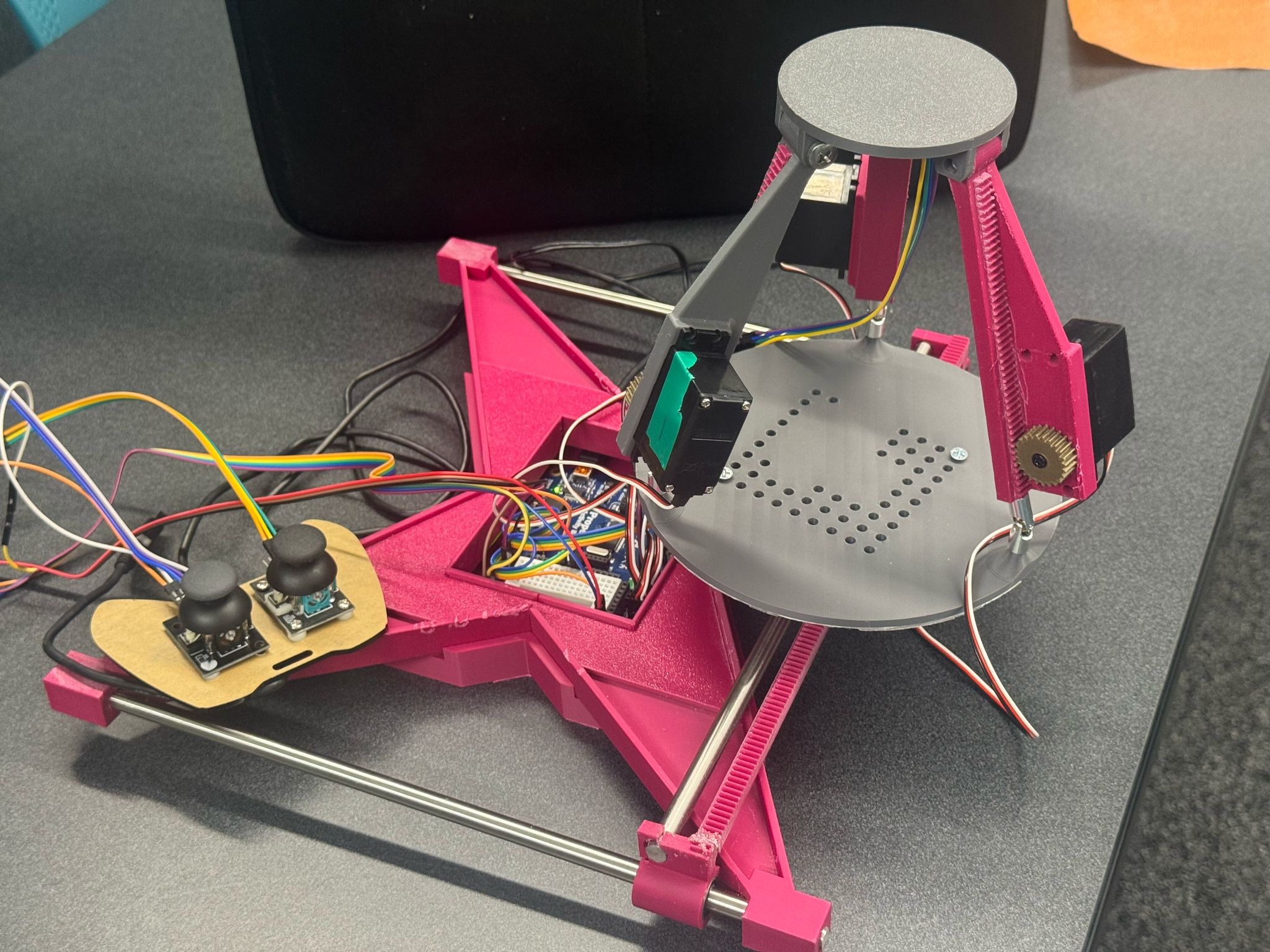
Complete 3-RPS gantry system overview
Prototype demonstration
System testing and validation
Troubleshootinng (dev stage)